Flowline, a Choke and a PDG
Add choke, PDG, and flowline elements to the One Flow model.
This tutorial adds optional features that increase the complexity of the system: a choke, a Pressure Downhole Gauge (PDG), and a flowline. Complete previous tutorial and keep the saved file before continuing.
Video tutorial coming soon
A YouTube walkthrough will be embedded here.
1. Upload the File
- Select Home in the sidebar.
- Select Clear All Data to start from a clean model.
-
Select Upload File and choose the file saved in the previous tutorial, for example
model_well_tutorial_1_oneflow_YYYYMMDD.
2. Add a Choke and PDG
- Select Simulation in the sidebar.
- Enter Choke. Use
120. - Enter PDG MD. Use
1600.
Chokes are commonly described in 64ths of an inch. A 120/64 choke corresponds to 1.875 in, but TapirFlow
only requires the value 120. In this fictional well, the tubing ends at 1700 m, so a PDG at
1600 m is a reasonable location.
- Select Home in the sidebar.
- Enter Model Name. Use
Well Tutorial-2. - Enter Model Description. Keep
Tutorial to get used to TapirFlow.
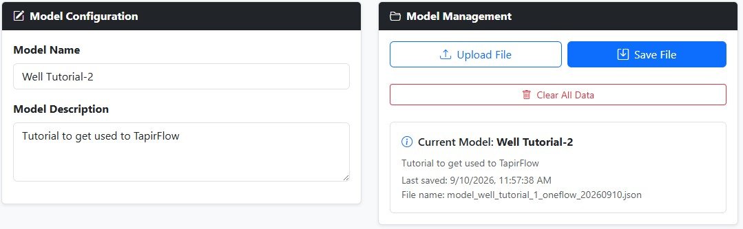
Select Save File. TapirFlow will save a file named
model_well_tutorial_2_oneflow_YYYYMMDD. Move it to your Tutorials
folder.
3. Run the One Flow Simulation
- Select Simulation in the sidebar.
- Select Run One Flow.
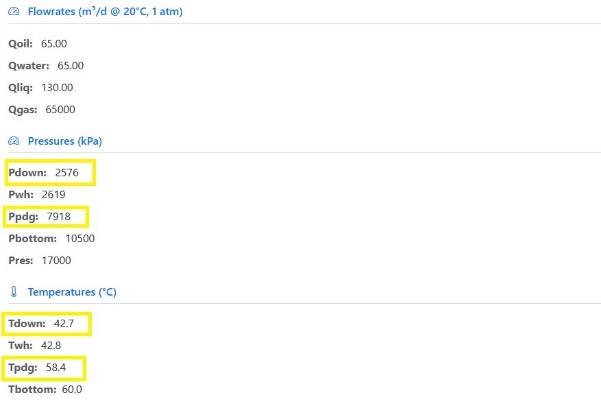
Pwh and Twh remain the same as in Tutorial 1. The results now also include Pdown and Tdown, which are the pressure and temperature downstream of the choke. Also include Ppdg and Tpdg, which are the pressure and temperature of the PDG.
4. Add a Flowline
- Select Flowline in the sidebar and check Incorporate flowline data into the simulation.
- Enter Rugosity. Use
0.05. - Enter Heat Coefficient. Use
30. - Go to + Add Segment.
- Enter Pipe ID for both segments. Use
76.2. - Enter Length for both segments. Use
1000. -
Enter High as
10for the first segment and-10for the second.
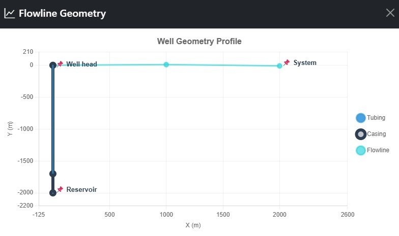
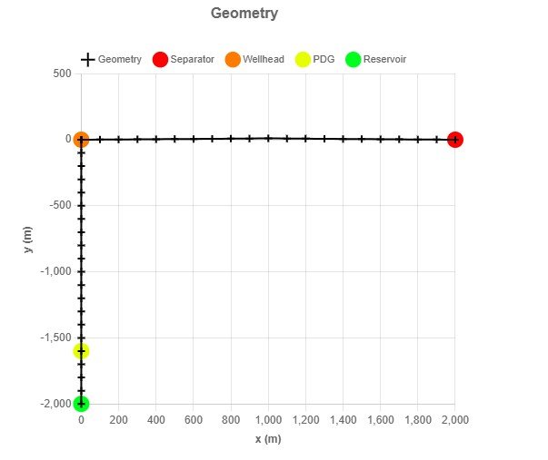
A pipe ID of 76.2 mm corresponds to a typical 3 in flowline. The elevation profile makes the fictional flowline rise for 1 km and then fall for another 1 km.
Select Show Geometry to view the integrated well and flowline geometry.
- Select Home in the sidebar.
- Enter Model Name. Use
Well Tutorial-2part2. - Enter Model Description. Keep
Tutorial to get used to TapirFlow.
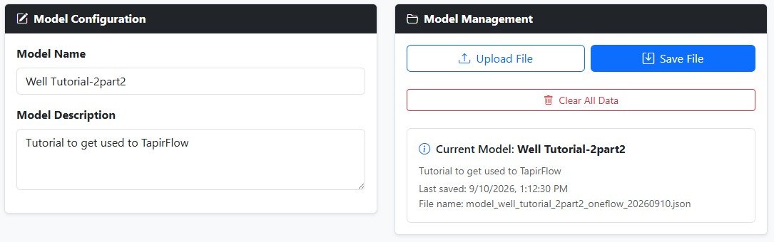
Select Save File. TapirFlow will save a file named
model_well_tutorial_2part2_oneflow_YYYYMMDD. Move it to your
Tutorials folder.
5. Run the One Flow Simulation with Flowline
- Select Simulation in the sidebar.
- Select Run One Flow.
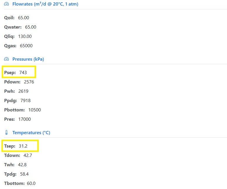
Pdown and Tdown remain the same as in the previous run. The results now also include Psep and Tsep, which are the pressure and temperature at the separator, the new final node.
Geometry Plot
6. Final Discussion and Exercise
In this example, Pwh is 2619 kPa, Pdown is 2576 kPa, and Psep is 743 kPa. These components add pressure drops, as expected.
As an exercise, increase the last flowline segment length from 1000 to 2000
and run a new One Flow simulation. The total flowline length becomes 3000 m.
You will notice that a warning message is shown.
Open the plot Pressure Profile for Flowline.
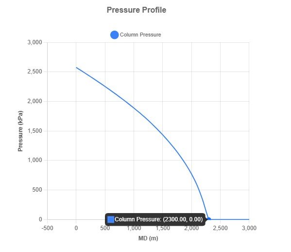
- The wellhead is always at MD = 0 m.
- The flowline is counted as positive MD until the final node. In this example, the separator is at MD = 3000 m.
- At approximately MD = 2300 m, the pressure becomes zero because there is not enough pressure to sustain the 65 m³/d oil flow rate until the end. This scenario is not feasible.